The direction of current in a circuit is one of the first things GCSE physics asks you to get right, and one of the easiest to get backwards. Ask which way the current flows and most textbooks say “from positive to negative”. Ask which way the electrons flow and the answer is the opposite. Both statements are correct, and this article shows you why, using a hands-on practical you can do in a school lab: a switch and lamp, a reversed cell, and a centre-zero galvanometer.
You will meet conventional current vs electron flow, the full set of GCSE circuit symbols, the four key quantities (charge, current, potential difference and resistance), the equations Q = It and V = IR, and 12 worked maths questions with click-to-reveal solutions. If you are a Sri Lankan Grade 10–11 science student or a teacher looking for a practical manual, the method is written out step by step.
What is the direction of current?
The direction of current is the way conventional current flows: out of the positive terminal of the cell, round the circuit, and back into the negative terminal. The electrons that actually carry the current in a metal wire move the opposite way, from the negative terminal towards the positive terminal. In GCSE exam questions, “current” always means conventional current.
That short answer is worth memorising, but it helps to know what current is. Electric current is a flow of electrical charge, and its size is the rate of flow of charge. The more charge passing a point each second, the bigger the current. It is measured in amperes (A), and one ampere is one coulomb of charge per second.
Charge only flows if the circuit is a complete, closed loop and contains a source of potential difference, such as a cell or battery. You will test this with a switch and lamp below.
Conventional current vs electron flow
Two different pictures of the same circuit sit side by side in physics, and they point in opposite directions. Students lose marks when they mix them up, so it is worth separating them carefully.
What is conventional current?
Conventional current is defined as the direction in which positive charges would flow. Draw a circuit diagram with a cell, and the arrows showing current leave the positive terminal, travel round through the components and return to the negative terminal. This is the direction used in almost every exam answer, circuit diagram and rule in GCSE physics.
Which way do electrons flow?
In a metal, the charge carriers are electrons, and electrons are negatively charged. They are pushed away from the negative terminal of the cell and drawn towards the positive terminal, so the direction of electron flow is from negative to positive. Edexcel’s specification states it plainly: the current in metals is a flow of electrons. If you want a refresher on why electrons carry a negative charge, our guide to sub-atomic particles in the atom covers it.
| Conventional current | Electron flow | |
|---|---|---|
| Direction in a circuit | From the positive terminal to the negative terminal | From the negative terminal to the positive terminal |
| What is moving | Imagined positive charges | Real electrons in a metal |
| Sign of the charge | Positive | Negative |
| Arrow on a circuit diagram | Points away from the long line of the cell symbol | Points the other way (drawn only when asked) |
| Where you use it | Exam answers, circuit diagrams, Fleming’s left-hand rule | Explaining what happens inside metal wires |
Why the convention points the “wrong” way
The reason is historical. Benjamin Franklin gave electric charges the names positive and negative, and he thought the thing that moved was positive. Long before anyone could test that idea, the direction “from positive to negative” was written into diagrams, books and rules.
It was not until 1897 that J. J. Thomson was credited with discovering the electron, showing that cathode rays are made of particles. By then the convention was so widely used that it simply stayed. Nothing about the physics is wrong; it is a label that was chosen before the facts were known. Our article on static electricity explores the charges Franklin was naming.
Does it matter which one you use?
For calculations, no. A negative charge moving one way has the same effect as a positive charge moving the other way, so your answers come out the same whichever direction you assume, as long as you stay consistent. Charge flow, current, potential difference and resistance do not depend on the choice.
For rules that depend on direction, you must follow the convention. Fleming’s left-hand rule, used for the force on a wire in a magnetic field and the basis of the electric motor, takes the second finger as conventional current, from positive to negative. Use electron flow there and you will predict the force in the wrong direction.
How fast do electrons move?
Switch on a torch and the lamp lights almost instantly, so you might think the electrons rush through the wire. They do not. In a copper wire of cross-section 1 mm² carrying 1 A, the electrons drift at only about 0.07 millimetres per second. The energy and the “push” travel far faster, at a significant fraction of the speed of light.
Think of a pipe already full of marbles: push one in and another pops out at once. The wire is already full of electrons, so they all start to drift together the moment the circuit is completed.
One direction or both: direct and alternating current
A cell or battery pushes current round the circuit in one direction only. We call this direct current (dc), and everything in the practical below uses it. UK mains electricity is different: it is alternating current (ac) at 50 Hz and about 230 V, and its direction keeps reversing. For that reason you must never use mains in a school practical; low-voltage cells are used instead.
Some components are fussy about direction. A diode lets current flow one way only and has a very high resistance in the reverse direction. An LED, a light-emitting diode, behaves the same way, so it makes a simple direction detector: it lights when connected one way round and stays dark the other. A motor and a centre-zero galvanometer are two more direction detectors, and you will use both shortly.
Now see the direction of current for yourself in the practical below.
Direction of current practical: what you need
This direction of current practical has three activities. In the first you build a switch and lamp circuit and see that a complete loop is needed. In the second you reverse the cell and watch a motor change direction. In the third (in the next section) you use a centre-zero galvanometer to see the reversal directly.
Apparatus
- Two 1.5 V cells (AA) in holders. The button end of an AA cell is positive and the flat end is negative.
- A torch lamp in a holder.
- A switch.
- A small dc motor with a paper flag or a small fan blade on the spindle, so you can see which way it turns.
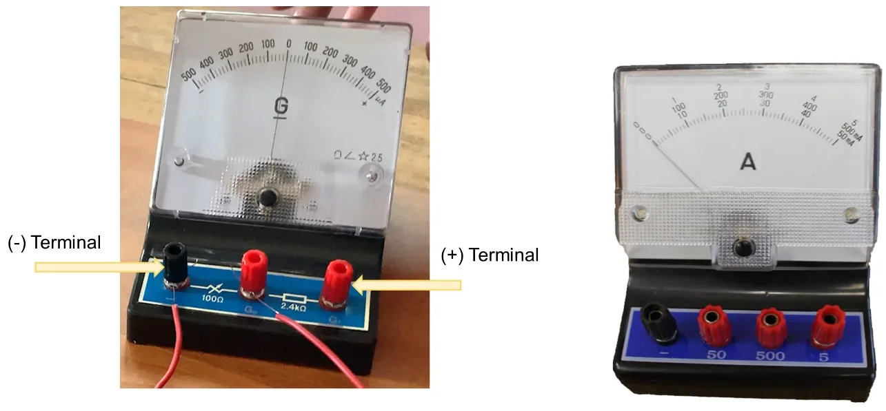
- A centre-zero galvanometer (scale 500–0–500 µA).
- A 10 kΩ resistor to protect the galvanometer.
- Connecting leads with crocodile clips: red for the positive side and black for the negative side.
- Optional: an LED with a protective resistor.
Risk assessment
The voltages are tiny, but a few simple precautions keep the equipment and the people safe. Use low-voltage cells only and never mains electricity.
| Hazard | Risk | Control |
|---|---|---|
| Short circuit | A wire connected straight across a cell makes the wire and cell hot | Never join the two terminals of a cell with a lead alone; switch off between readings |
| Galvanometer overload | Too large a current can damage the meter or bend the needle | Always put the 10 kΩ resistor in series; never connect the galvanometer straight across a cell |
| Mains electricity | Serious injury | Use only 1.5–3 V cells in this practical |
| Damaged or leaking cells | Skin irritation | Do not use them; do not open or recharge non-rechargeable cells; wash your hands afterwards |
Circuit symbols you need for this practical
Circuit diagrams are the language of electricity, and the GCSE specification expects you to recognise 14 symbols. Edexcel adds the motor to its list. In the cell symbol, the longer line is the positive terminal, and the conventional-current arrows on a diagram point away from that long line.
| Symbol | What it looks like | What it does |
|---|---|---|
| Cell | A long line and a short line side by side; the long line is + | Provides a potential difference |
| Battery | Two or more cells joined, long line + | Provides a larger potential difference |
| Switch (open) | A lever raised, leaving a gap | Breaks the circuit, so no current |
| Switch (closed) | The lever closed across the gap | Completes the circuit |
| Lamp | A circle with a cross inside | Transfers energy as light and heat |
| Fuse | A small rectangle with a line through it | Breaks the circuit if the current is too large |
| Voltmeter | A circle with V | Measures potential difference; connected in parallel |
| Ammeter | A circle with A | Measures current; connected in series |
| Resistor | A plain rectangle | Limits the current |
| Variable resistor | A rectangle with a diagonal arrow through it | Resistance can be changed |
| Diode | A triangle pointing at a bar, inside a circle | Lets current flow one way only |
| LED | The diode symbol with two arrows pointing outwards | Emits light; one-way like a diode |
| Thermistor | A rectangle with a diagonal line that has a short flat end | Resistance depends on temperature |
| LDR | A rectangle inside a circle with two arrows pointing inwards | Resistance depends on light level |
| Motor (Edexcel list) | A circle with M | Turns electrical energy into movement |
Activity 1: the switch and lamp circuit
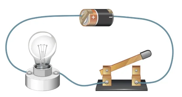
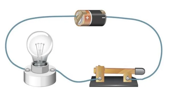
- With the switch open, join the cells, switch and lamp in one loop using the leads.
- Look at the lamp with the switch open. Record what you see.
- Close the switch and look at the lamp again. Record what you see.
- Open the switch again, then add an ammeter in series on one side of the lamp. Close the switch and read the current.
- Move the ammeter to the other side of the lamp and read it again.
With the switch open there is a gap in the loop, so charge cannot flow and the lamp stays off. Closing the switch completes the circuit, and because the circuit includes the cells as a source of potential difference, there is a current. You should find that the ammeter reads the same on both sides of the lamp. In a single closed loop the current has the same value at every point, so the lamp does not use any of it up.
Activity 2: reverse the cell (motor test)
A motor is a handy direction detector because its spin depends on the direction of the current through it.
- Connect the red clip from the positive end of the cell to one motor terminal and the black clip from the negative end to the other. Add the switch in the loop.
- Close the switch, watch the motor and note whether the flag turns clockwise or anticlockwise. Open the switch.
- Swap the two clips on the motor terminals (or turn the cell round) so the current is reversed.
- Close the switch and note the direction of spin again.
The motor spins the opposite way when the cell is reversed. The reason is that a coil carrying a current in a magnetic field experiences a force, and Fleming’s left-hand rule gives the direction of that force from the field and the current. Reverse the current and the force on the coil reverses, so the motor turns the other way. This is the basis of the electric motor, and the same idea drives the motors in electric cars.
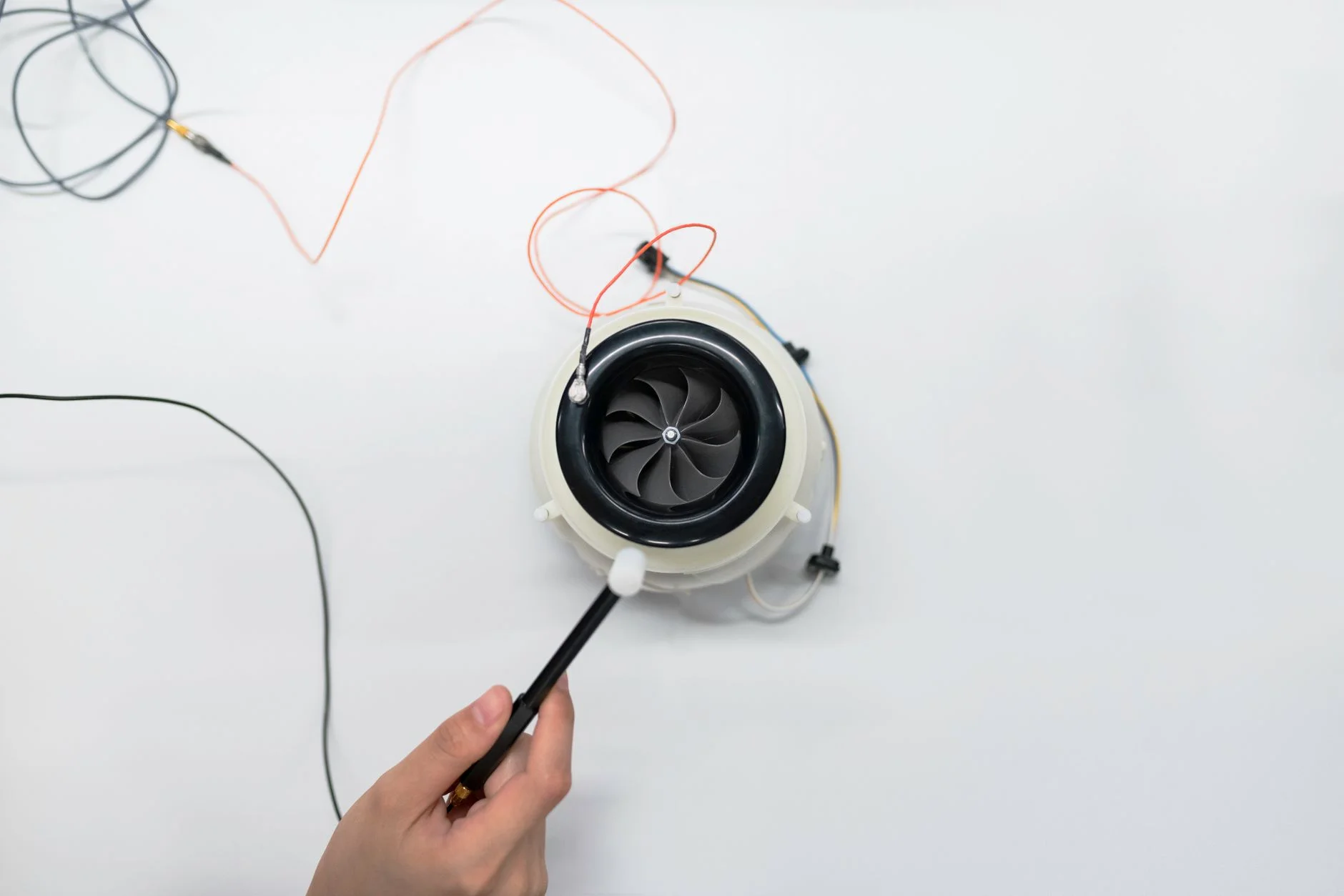
Be careful what this proves: the motor shows that the current has reversed, not which way the charge “really” moves.
Results table
Here is how your results might look. These are example observations, not measured data, so your own notes may differ in wording.
| Activity | Connection | Observation |
|---|---|---|
| 1. Switch and lamp | Switch open | Lamp off, no current |
| 1. Switch and lamp | Switch closed | Lamp on, current flows; ammeter reads the same either side of the lamp |
| 2. Motor | Red clip to motor terminal A | Flag turns clockwise (for example) |
| 2. Motor | Clips swapped | Flag turns anticlockwise |
| Optional: LED | One way round, then the other | Lights one way only (a diode passes current in one direction) |
Check before you switch on
Run through this list every time. It takes ten seconds and protects both the equipment and your results. Your ticks are remembered in your browser.
- The cells are in the holders the right way round (button end positive).
- The 10 kΩ resistor is in series with the galvanometer.
- The switch is open while I connect the leads.
- No bare wires or crocodile clips are touching each other.
- I am using 1.5–3 V cells only, never mains.
How a centre-zero galvanometer shows the direction of current
A galvanometer is an electromechanical instrument for detecting and measuring electric current. It is named after Luigi Galvani, and the earliest galvanometer was reported by Johann Schweigger in 1820. A centre-zero galvanometer has its zero in the middle of the scale. When current flows through it one way, the needle swings to one side; when the current is reversed, the needle swings to the other side. The size of the swing shows the size of the current, and the side it swings to shows the direction.
Our galvanometer has a scale marked 500–0–500 µA (microamps) and the letter G. It has a black terminal marked − and two red terminals marked G0 and G1, and the numbers 100 Ω and 2.4 kΩ are printed on its base. Full scale is only 500 µA, which is 0.0005 A, so it needs protecting.
Activity 3: reverse the cell and watch the needle
- Join one 1.5 V cell, the 10 kΩ resistor, the switch and the galvanometer in one series loop. The resistor is essential. Without it the current could be far above full scale.
- Close the switch briefly and note two things: which side the needle swings to, and how far it moves.
- Open the switch. Reverse the cell (or swap the leads on the galvanometer).
- Close the switch briefly again. Note the side and the size of the swing.
The needle swings the same distance but to the opposite side. Your conclusion: reversing the cell reverses the direction of the current, but the size of the current does not change, because the resistance and the potential difference are the same. A centre-zero meter can be connected either way round without harm, and that is the point of it: the side of the swing tells you the direction.
The galvanometer can detect the tiny current from a chemical cell, as in our simple cell experiment, and from a fruit, as in the lemon battery experiment. It also swings both ways in electromagnetic induction.
Measuring current: ammeters and galvanometers
To measure the size of a current in a circuit, you connect an ammeter in series with the component, so the current you want to measure passes through the meter. A voltmeter measures potential difference and is connected in parallel across the component.
Galvanometers and ammeters are close relatives. Calibrated galvanometers became ammeters, and by adding a shunt (a low-resistance path alongside the meter) a meter can be made to measure much larger currents. The two differ in practical ways:
- Centre-zero galvanometer: zero in the middle, detects very small currents, shows direction as well as size.
- Ordinary ammeter: zero at one end, reads current in one direction only, usually with several ranges in mA or A.
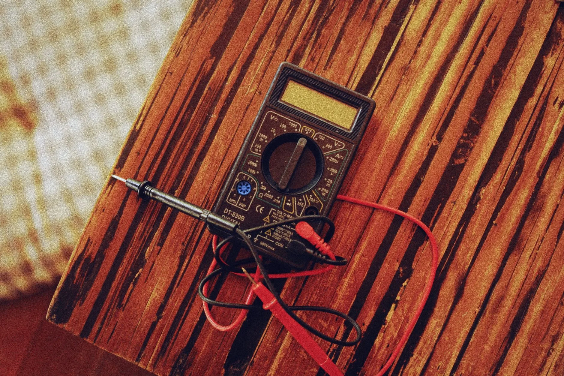
Why can’t an ordinary ammeter tell you the direction of current? (2 marks)
Its zero is at one end of the scale, so it can only show current in one direction. If the current is reversed, the needle tries to move below zero instead of swinging to the other side. A centre-zero meter has its zero in the middle, so the needle swings either way.
Charge, current, potential difference and resistance
Four quantities appear together in every GCSE electricity question. Learn each name, its unit and its symbol, and you will find the equations much easier. Tap each card to check yourself.
AQA sets questions using “potential difference” and credits either that or “voltage”.
Q = It: charge flow = current × time
The first equation links charge to current. Because current is the rate of flow of charge, the charge that flows is the current multiplied by the time. You must be able to recall and apply it.
charge flow (C) = current (A) × time (s) Q = I t
Worked example: a current of 0.40 A flows for 30 s. Q = I × t = 0.40 × 30 = 12 C. Remember that time must be in seconds and current in amperes, so convert minutes (× 60) and milliamps or microamps (÷ 1,000 or ÷ 1,000,000) first.
You can connect this to the electrons. One electron carries 1.602 176 634 × 10⁻¹⁹ C, an exact, defined value, so one coulomb is about 6.24 × 10¹⁸ electrons.
V = IR: potential difference = current × resistance
The second equation links the other two quantities. The current through a component depends on both the resistance of the component and the potential difference across it.
potential difference (V) = current (A) × resistance (Ω) V = I R
Worked example: a current of 0.10 A flows through a 30 Ω resistor. V = I × R = 0.10 × 30 = 3.0 V. Rearranged, I = V ÷ R and R = V ÷ I.
Two rules for simple circuits help with longer questions. In a series circuit the current is the same through each component, the supply p.d. is shared between them, and the total resistance is R₁ + R₂. In a parallel circuit the p.d. across each branch is the same, and the total current is the sum of the branch currents.
Try your own numbers in the calculator below; leave the resistance as 0 if you only need the charge.
Now practise the arithmetic on the 12 maths questions below.
Maths practice questions
These 12 questions are graded: Q1–4 are foundation, Q5–9 higher and Q10–12 stretch. Use e = 1.60 × 10⁻¹⁹ C where needed. Try each on paper first, then tap to reveal the worked solution.
Q1. A current of 0.50 A flows through a lamp for 60 s. Calculate the charge that flows. (2 marks)
Q = I × t = 0.50 × 60 = 30 C.
Q2. A torch lamp carries 2.0 A for 5.0 minutes. Calculate the charge flow. (3 marks)
Convert the time: t = 5.0 × 60 = 300 s. Then Q = I × t = 2.0 × 300 = 600 C.
Q3. 45 C of charge passes a point in 15 s. Calculate the current. (2 marks)
I = Q ÷ t = 45 ÷ 15 = 3.0 A.
Q4. How long does it take for 1,200 C to flow at a current of 4.0 A? Give your answer in minutes. (3 marks)
t = Q ÷ I = 1,200 ÷ 4.0 = 300 s. In minutes: 300 ÷ 60 = 5.0 minutes.
Q5. A centre-zero galvanometer reads 250 µA for 2.0 minutes. Calculate the charge that flows. (3 marks)
I = 250 µA = 250 × 10⁻⁶ A = 2.5 × 10⁻⁴ A. t = 2.0 × 60 = 120 s. Q = I × t = 2.5 × 10⁻⁴ × 120 = 0.030 C (3.0 × 10⁻² C).
Q6. A resistor of 12 Ω carries a current of 0.25 A. Calculate the potential difference across it. (2 marks)
V = I × R = 0.25 × 12 = 3.0 V.
Q7. Two 1.5 V cells are joined in series to a torch lamp. The current is 0.20 A. Calculate the resistance of the lamp. (Assume all the p.d. is across the lamp.) (3 marks)
Total p.d. V = 1.5 + 1.5 = 3.0 V. R = V ÷ I = 3.0 ÷ 0.20 = 15 Ω.
Q8. A 9.0 V supply is connected across a 180 Ω resistor. (a) Calculate the current in mA. (b) Calculate the charge that flows in 1.0 minute. (4 marks)
(a) I = V ÷ R = 9.0 ÷ 180 = 0.050 A = 50 mA.
(b) t = 60 s, so Q = I × t = 0.050 × 60 = 3.0 C.
Q9. The charge on one electron is 1.60 × 10⁻¹⁹ C. How many electrons pass a point each second when the current is 1.0 A? (2 marks)
1.0 A is 1.0 C per second. Number of electrons = 1.0 ÷ 1.60 × 10⁻¹⁹ = 6.25 × 10¹⁸ electrons per second. Using the exact value of e gives 6.24 × 10¹⁸. To 2 significant figures these are 6.3 × 10¹⁸ and 6.2 × 10¹⁸, so accept either.
Q10. A current of 0.30 A flows for 10 s. Calculate (a) the charge and (b) the number of electrons that pass. (e = 1.60 × 10⁻¹⁹ C) (3 marks)
(a) Q = I × t = 0.30 × 10 = 3.0 C.
(b) Number of electrons = 3.0 ÷ 1.60 × 10⁻¹⁹ = 1.875 × 10¹⁹ ≈ 1.9 × 10¹⁹ electrons (2 significant figures).
Q11. Stretch: protecting the galvanometer. The galvanometer’s full-scale reading is 500 µA. It is used with a 1.5 V cell. (a) Calculate the smallest total resistance that keeps the current on the scale. (b) A 10 kΩ resistor is used instead (ignore the meter’s own resistance). Calculate the reading. (c) What happens to the reading when the cell is reversed? (4 marks)
(a) I = 500 µA = 5.0 × 10⁻⁴ A. R = V ÷ I = 1.5 ÷ 5.0 × 10⁻⁴ = 3,000 Ω (3.0 kΩ).
(b) I = V ÷ R = 1.5 ÷ 10,000 = 1.5 × 10⁻⁴ A = 150 µA.
(c) The needle swings to 150 µA on the other side of zero: same size, opposite direction.
Q12. Stretch: series circuit. A 6.0 V battery is connected to a 10 Ω resistor and a 20 Ω resistor in series. Calculate (a) the total resistance, (b) the current, (c) the p.d. across the 20 Ω resistor, (d) the charge that flows in 2.0 minutes, (e) the energy transferred by the battery in that time (E = Q V). (5 marks)
(a) R = 10 + 20 = 30 Ω.
(b) I = V ÷ R = 6.0 ÷ 30 = 0.20 A.
(c) V = I × R = 0.20 × 20 = 4.0 V (and 2.0 V across the 10 Ω, so they add to 6.0 V).
(d) t = 120 s, so Q = 0.20 × 120 = 24 C.
(e) E = Q × V = 24 × 6.0 = 144 J.
Exam-style questions and required practical links
Try these three command-word questions before revealing the model answers.
Describe how a centre-zero galvanometer can be used to show that reversing a cell reverses the current. (3 marks)
Connect the galvanometer in series with the cell and a large resistor. Note the direction the needle deflects. Reverse the cell, and the needle deflects by the same amount in the opposite direction, showing the current has reversed.
Explain why the current in a metal wire is in the opposite direction to the electron flow. (2 marks)
Conventional current is defined as the direction in which positive charges would flow, from positive to negative. Electrons are negatively charged, so they move the other way, from negative to positive.
A student says the current is bigger before the lamp than after it. Explain why the student is wrong. (2 marks)
In a single closed loop the current has the same value at every point. The lamp does not use up charge; it transfers energy from the circuit to its surroundings.
This activity is not itself an AQA required practical, but it builds skills used in two of them. AQA required practical 3 covers factors affecting resistance (the length of a wire at constant temperature) and resistors in series and parallel. Required practical 4 covers the I–V characteristics of a filament lamp, a diode and a resistor at constant temperature. In that second practical you reverse the supply to get negative readings, which is the same idea as reversing the cell here.
Common mistakes and exam tips
- Drawing electron flow when the question says “current”. Current means conventional current, from positive to negative.
- Saying a lamp “uses up” current. Current is the same at every point in a single loop; energy is what is transferred.
- Putting the ammeter in parallel. An ammeter goes in series and a voltmeter goes in parallel.
- Forgetting unit conversions. Change µA and mA to A, and minutes to seconds, before using Q = It or V = IR.
- Mixing up “voltage” and “potential difference”. Either is credited, but learn “potential difference” as the proper term.
- Connecting a microamp galvanometer straight across a cell. Always include a large resistor in series.
A potential difference is needed for current, which is why birds can perch on a single wire: there is no p.d. across the bird. The equation Q = It also returns in A-level electrolysis calculations, so see what electrolysis is for more practice.
Frequently asked questions about the direction of current
What is the direction of current in a circuit?
The direction of current is the direction of conventional current: out of the positive terminal of the cell, round the circuit and back into the negative terminal. Electrons in metal wires move the opposite way. In GCSE questions, “current” means conventional current.
Does current flow from positive to negative?
Yes, by convention. Conventional current is defined as the direction in which positive charges would flow, from the positive terminal to the negative terminal. Electrons in a metal move from negative to positive, but we draw the current arrow from positive to negative.
Why is conventional current opposite to electron flow?
Benjamin Franklin named charges positive and negative, and he thought the moving charge was positive. The electron was not discovered until 1897, by J. J. Thomson. By then the convention was used everywhere, so it stayed.
Which way do electrons flow in a circuit?
Electrons flow from the negative terminal of the cell, through the wires and components, to the positive terminal.
How does a centre-zero galvanometer show the direction of current?
A centre-zero galvanometer has its zero in the middle of the scale. Current in one direction swings the needle to one side, and current in the opposite direction swings it to the other side. The distance the needle moves shows the size of the current, so the meter shows both size and direction.
What is the difference between a galvanometer and an ammeter?
A galvanometer detects and measures small currents, and a centre-zero type shows direction too. An ordinary ammeter has zero at one end, so it reads current in one direction only, usually over several ranges.
How many electrons make one coulomb of charge?
One electron carries 1.602 176 634 × 10⁻¹⁹ C, an exact, defined value. Dividing 1 C by this gives about 6.24 × 10¹⁸ electrons in one coulomb. Using 1.60 × 10⁻¹⁹ C gives 6.25 × 10¹⁸, which differs from the exact-value answer by only about 0.1%.
What do Q = It and V = IR mean?
Q = It means charge flow in coulombs equals current in amperes multiplied by time in seconds. V = IR means potential difference in volts equals current in amperes multiplied by resistance in ohms. Both are equations you must recall and apply at GCSE, so always convert units to A and s first.
Is the current the same everywhere in a series circuit?
Yes. In a single closed loop the current has the same value at any point, so an ammeter reads the same on either side of a lamp. The lamp transfers energy, not charge.