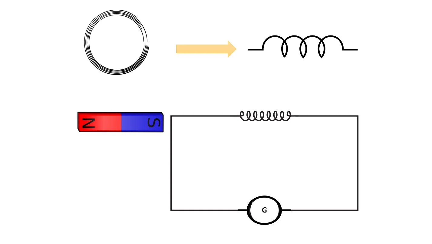
Push a bar magnet into a coil of wire and the needle on a meter kicks to one side. Pull the magnet out and the needle kicks the other way. Hold it still and the needle sits on zero. That is the electromagnetic induction experiment, and it is one of the neatest demonstrations in GCSE physics because there is no battery anywhere in the circuit.
The same effect, called the generator effect, makes electricity in a bicycle dynamo, a wind turbine and a hydroelectric power station. This article gives you the full practical write-up (apparatus, method, risk assessment, results and evaluation), then the theory the exam tests, then 12 worked maths questions with click-to-reveal solutions.
What is electromagnetic induction (the generator effect)?
Electromagnetic induction means making a potential difference (p.d.) in a conductor by using a magnetic field instead of a cell. AQA GCSE Physics puts it like this: if an electrical conductor moves relative to a magnetic field, or if there is a change in the magnetic field around a conductor, a potential difference is induced across the ends of the conductor.
If the conductor is part of a complete circuit, that induced p.d. pushes a current round it. AQA calls this the generator effect. Notice the careful wording: the p.d. is induced whether or not the circuit is complete, but a current only flows when there is a complete circuit. Examiners reward students who say "induced potential difference" rather than just "voltage".
Two words in the definition matter most: relative and change. A magnet sitting next to a wire does nothing. It is the movement, or the change in the field, that does the job. You will see this directly in the results later. If you want the bigger picture of how machines use the effect, how generators work covers it from the engineering side.
Where electromagnetic induction sits in the GCSE specification
Check your own exam board, because the tiering differs between courses. In AQA GCSE Physics (8463) it is section 4.7.3, "Induced potential, transformers and the National Grid", and it is marked physics only and Higher tier only. That means it is not in AQA Combined Science. Edexcel and OCR cover the same ideas in their own physics courses, so the method and the theory below still apply.
Electromagnetic induction experiment: apparatus
This is the classic "magnet and coil" experiment, and it needs very little kit. You can see the circuit in the diagram at the top of this page: a coil of wire drawn as a circuit symbol, joined in a loop to a galvanometer marked G, with a bar magnet beside the coil.
- A coil of insulated copper wire, either a ready-made solenoid or a coil with a few tens of turns wound on a card tube.
- A bar magnet with its poles marked N and S. Later you will swap it for a stronger magnet to test one of the factors. If you are curious how magnet strength is compared, see the strongest magnets in the world.
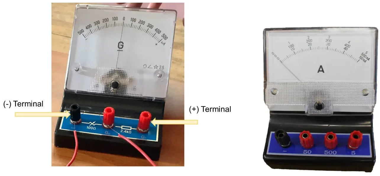
- A centre-zero galvanometer (a sensitive meter for very small currents).
- Two connecting leads, long enough that you can move the coil or magnet freely.
- Optional: a second coil with more turns, for the "number of turns" test.
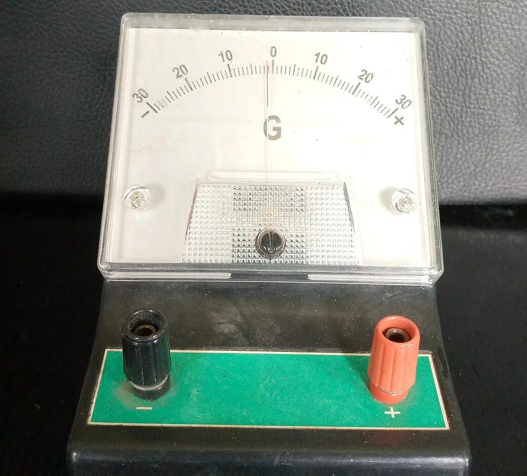
Why a centre-zero galvanometer? Its zero is in the middle of the scale, so the needle can swing either way. That means it shows the direction of the current as well as its size. An ordinary ammeter with its zero at the left-hand end would just push the needle against the stop when the current flows the wrong way. If you want to see how meters and current direction connect, there is a full guide in direction of current: the practical manual.
If your school only has a meter with zero at the left, ask your teacher about the zero-adjust screw, which can sometimes move the needle's resting position onto the scale so that it can still swing both ways.
Method: moving a magnet through a coil of wire
Work through these steps in order and tick them off as you go. Your ticks are remembered in your browser, so you can come back to the list during the practical.
- Connect the two ends of the coil to the terminals of the galvanometer with the leads, as in the circuit diagram at the top of this page.
- Check that the needle rests on zero with the magnet well away from the coil.
- Push the north pole of the bar magnet quickly into the coil. Watch the needle and note which way it moves and how far.
- Hold the magnet still inside the coil for a few seconds. Note the reading.
- Pull the magnet quickly out of the coil. Note the direction and size of the deflection.
- Repeat the push-in and pull-out with the south pole entering first.
- Repeat the push-in again, first slowly and then as fast as you can. Compare the sizes of the deflections.
- Swap in a coil with more turns, then a stronger magnet, and repeat the same quick push-in each time.
- Finally, keep the magnet still and move the coil over it instead. Note what happens.
Keep a table ready before you start so you can record every action and the needle's response. A neat results table is half the marks in any practical write-up, and a sample is given in the results section below.
Risk assessment
This is a low-risk practical. No mains electricity is used and nothing is heated; the only "power supply" is your own hand. The hazards come from the magnets.
| Hazard | Risk | Control |
|---|---|---|
| Strong magnets snapping together | Pinched fingers or skin | Handle one strong magnet at a time and slide magnets apart rather than pulling them straight off each other. |
| Magnets slamming together | Brittle neodymium magnets can chip or shatter, sending sharp fragments flying | Wear eye protection when using neodymium magnets and keep them apart on the bench. |
| Dropped bar magnets | Chipping, and some types can be weakened | Work over the bench, not at arm's length in the air, and store them safely. |
| Magnets near phones, bank cards or the meter | Damage to equipment | Keep magnets away from phones and cards, and from the meter itself. |
Also keep strong magnets away from young children, because swallowed magnets are dangerous, and away from anyone with a pacemaker or other implanted medical device. Your teacher will have a school risk assessment that covers everything else; this table is a starting point, not a replacement.
Results: what the galvanometer shows
Here is the pattern you should see when you carry out the electromagnetic induction experiment. Whether the needle goes left or right depends on how your coil is wound and how it is connected, so the table says "one way" and "the opposite way". What matters is that the two directions are opposite.
| Action | Needle | Why |
|---|---|---|
| North pole pushed in quickly | Big deflection one way | The magnetic field through the coil is changing. |
| Magnet held still inside the coil | Zero | No change in the field, so no induced p.d. |
| North pole pulled out | Deflection the opposite way | The field is now changing in the opposite sense. |
| South pole pushed in | Opposite way to north pole going in | Reversing the magnet reverses the field direction. |
| North pole pushed in slowly | Smaller deflection | The field changes more slowly. |
| Coil with more turns | Bigger deflection | Each turn contributes to the induced p.d. |
| Stronger magnet | Bigger deflection | A stronger field means a bigger change as it moves. |
| Coil moved over a still magnet | Deflects | Only the relative motion matters. |
Notice that the needle only moves while something is moving. As soon as the magnet stops, the needle drifts back to zero, even if the magnet is deep inside the coil. This surprises many students, who expect a strong magnet inside a coil to keep "making electricity". It does not. A steady magnetic field gives no continuing induced p.d.
Electromagnetic induction experiment: factors affecting the induced potential difference
The size of the induced p.d. depends on how quickly the magnetic field through the coil changes. You can increase it in three main ways, plus one extra that some courses mention:
- Move the magnet (or the coil) faster. A higher speed (or faster rotation in a generator) makes a bigger induced p.d.
- Use a stronger magnet. A stronger field gives a bigger change.
- Use a coil with more turns. Each turn adds to the total.
- Use a coil with a larger area. Some specifications include this too.
All four of these increase how fast the magnetic field through the coil is changing. A common way to say this is that the coil "cuts more field lines every second". Two things change the direction of the induced p.d. and current: reversing the direction of the movement, or reversing the poles of the magnet (so the field direction is reversed). Reverse both at once and the direction stays the same as before.
Tap each card below to test yourself on the six key cause-and-effect pairs.
Which way does the induced current flow? Lenz's law
AQA states that an induced current generates a magnetic field that opposes the original change, either the movement of the conductor or the change in the magnetic field. This is known as Lenz's law, named after Heinrich Lenz, who formulated it in 1834.
Here is what that means in the experiment. Push the north pole of the magnet into the coil. The induced current flows in the direction that turns the near end of the coil into a north pole too. Two north poles repel, so the coil pushes back on the magnet. Pull the north pole out, and the near end of the coil becomes a south pole instead. It attracts the magnet and tries to hold it back.
Either way, the coil resists the motion. You have to push against it, which means you have to do work. That work is where the electrical energy comes from, so Lenz's law is really conservation of energy in action. It is also why a generator gets harder to turn when it is supplying more current. The idea of the coil "pushing back" links directly to the forces and energy ideas in Newton's laws of motion.
A-level stretch: Faraday's law
Conclusion, evaluation and variables
Conclusion. A potential difference is induced across the ends of a coil when a magnet moves relative to it. A current flows because the coil is part of a complete circuit. The p.d. is larger when the magnet moves faster, when the magnet is stronger and when the coil has more turns. It is zero when there is no relative movement. The direction reverses when the direction of movement or the magnet's poles are reversed.
If you test one factor at a time, you need to control the rest. A variables table makes this clear:
| Type | What it is |
|---|---|
| Independent variable | The one you change: speed of movement, number of turns or magnet strength |
| Dependent variable | The one you measure: the size of the galvanometer deflection |
| Control variables | Same coil, same meter, same magnet, same distance moved, same starting position |
Evaluation. The weakest point of this practical is the hand. It is very hard to push a magnet at exactly the same speed twice, and the needle only flicks for a moment, so you are reading a quick peak by eye. To improve it, you could drop the magnet through the coil from a fixed height each time so the speed is the same, record the maximum deflection from several repeats and take a mean, or film the needle in slow motion and replay it. A more sensitive meter, or a data logger connected across the coil, would make the readings more precise.
Another source of error is that your coil may have only a few tens of turns, so the deflections are small. A coil with more turns, or a stronger magnet, gives a clearer result. Repeat each test at least three times and discard any result that is clearly an outlier.
It also helps to place this practical in context. Electricity can be made in several ways in school physics, for example chemically in a cell, by movement and induction in a generator, and from light in a solar cell. Cells are explored in the simple cell experiment, which makes a useful contrast. A cell needs a chemical reaction; a generator needs movement. Neither one makes energy from nothing.
How a bicycle dynamo works
The bottle dynamo on an old bicycle is the most familiar everyday use of electromagnetic induction. A small wheel, called the roller, is pressed against the tyre. When the bike moves, the tyre spins the roller, and the roller spins a permanent magnet inside a fixed coil of wire.

The spinning magnet means the magnetic field through the coil is constantly changing, so a p.d. is induced in the coil. The coil is connected to the lamp, so a current flows and the lamp lights. Stop pedalling and the roller stops, the field stops changing and the lamp goes out. Pedal faster and the lamp is brighter, because faster movement means a bigger induced p.d. Traditional bottle dynamos and hub dynamos are typically rated 6 V, 3 W.
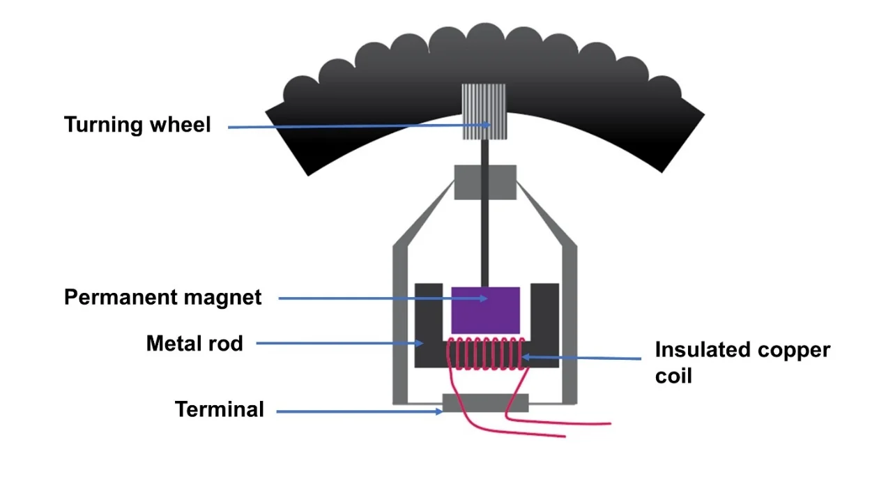
Walk through the labels on the diagram from the top. The turning wheel touches the tyre and is turned by it. The spindle carries that rotation down to the permanent magnet. The magnet's changing field is guided through the soft-iron core, which is labelled "metal rod" on the diagram. Wrapped around the core is the insulated copper coil, where the p.d. is induced. Finally, two wires carry the output to the terminal and on to the lamp.
AC generator (alternator) versus dynamo
AQA says the generator effect is used in an alternator to generate ac and in a dynamo to generate dc. In both, a coil rotates in a magnetic field (or a magnet rotates inside fixed coils), and an induced p.d. appears across the coil. The difference lies in how the coil is connected to the outside circuit.
| Alternator (AC generator) | Dynamo (DC generator) | |
|---|---|---|
| Output | Alternating: the p.d. reverses every half-turn | Direct: varies in size but never reverses |
| Connection | Slip rings and carbon brushes | Split-ring commutator, which swaps the connections every half-turn |
| p.d.–time graph | Sine-shaped wave crossing zero | A series of humps, all on the same side of zero |
| Examples | Power stations, car alternators, bottle "dynamos" | Old dynamos, simple demonstration generators |
One turn of the coil is one complete AC cycle. The p.d. is zero when the plane of the coil is at right angles to the field lines, because the coil is momentarily moving along the field instead of cutting across it. It is at a maximum when the plane of the coil is parallel to the field lines. Turning the coil faster gives taller peaks and peaks closer together, which means a bigger p.d. and a higher frequency.
Large power-station generators work the other way round: a spinning electromagnet (the rotor) turns inside fixed coils (the stator). The principle is exactly the same, and large generators convert mechanical energy to electrical energy at about 98% efficiency.
How hydroelectric power stations use induction
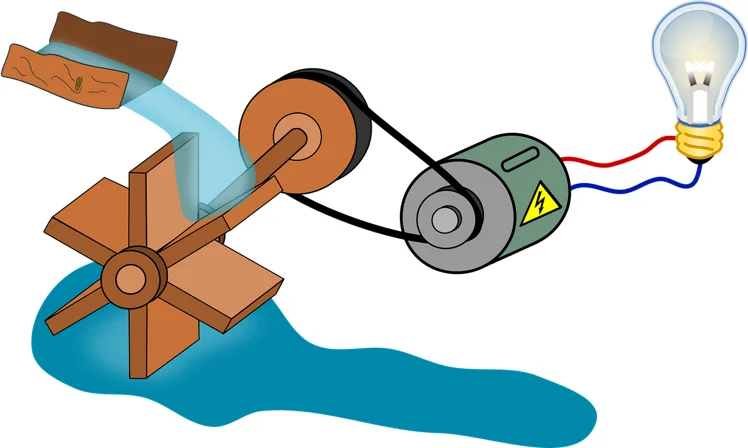
A hydroelectric station is the water-wheel picture scaled up. Water stored high up has energy in its gravitational potential energy store. When it flows downhill it gains kinetic energy and turns a turbine, and the turbine turns a generator. The generator is where electromagnetic induction happens.
Dinorwig, the "Electric Mountain" in Snowdonia, Wales, is a pumped-storage station built in the abandoned Dinorwic slate quarry. The power station sits deep inside the mountain Elidir Fawr, in tunnels and caverns. Six 300 MW generator/motors are coupled to reversible Francis turbines, giving a maximum output of 1,728 MW. With its turbines already spinning, it can go from zero to full output in about 16 seconds and keep it up for several hours.
Water falls from the Marchlyn Mawr reservoir, 636 m above sea level, to Llyn Peris, at about 100 m. At off-peak times the machines run in reverse as motors and pump the water back up, so the station acts as a giant store of energy. It connects to the National Grid by 400 kV cables buried for about 10 km.

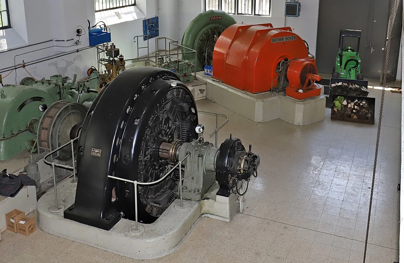
Pumped storage and dams have costs as well as benefits, and the good and bad of dams weighs them up.
Wind turbines: induction in the sky
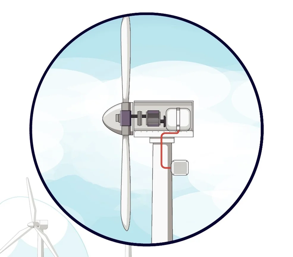
A wind turbine uses the kinetic energy of the wind to turn its blades. Inside the nacelle (the housing at the top), the slow rotor shaft often drives a gearbox, which speeds the rotation up for a fast-spinning generator. Others use a large, slow direct-drive generator with powerful neodymium permanent magnets instead. Either way, the generator effect does the work, and a cable carries the output down the tower.
A turbine generator typically produces about 690 V. A transformer at the base of each turbine steps that up to 33 kV, and a substation transformer steps it up again for the grid (132 kV in the example of the Loeriesfontein wind farm in South Africa). In 2025, wind supplied 29.5% (86.4 TWh) of UK electricity, the largest renewable source, according to DESNZ figures reported in August 2026. Renewables as a whole supplied 52.1%.
If you want to weigh the benefits and drawbacks, see the advantages and disadvantages of wind energy and renewable energy: expectations versus reality. For contrast, solar cells make electricity with no induction and no moving parts at all; how solar panels work explains how.
Transformers: induction without moving parts
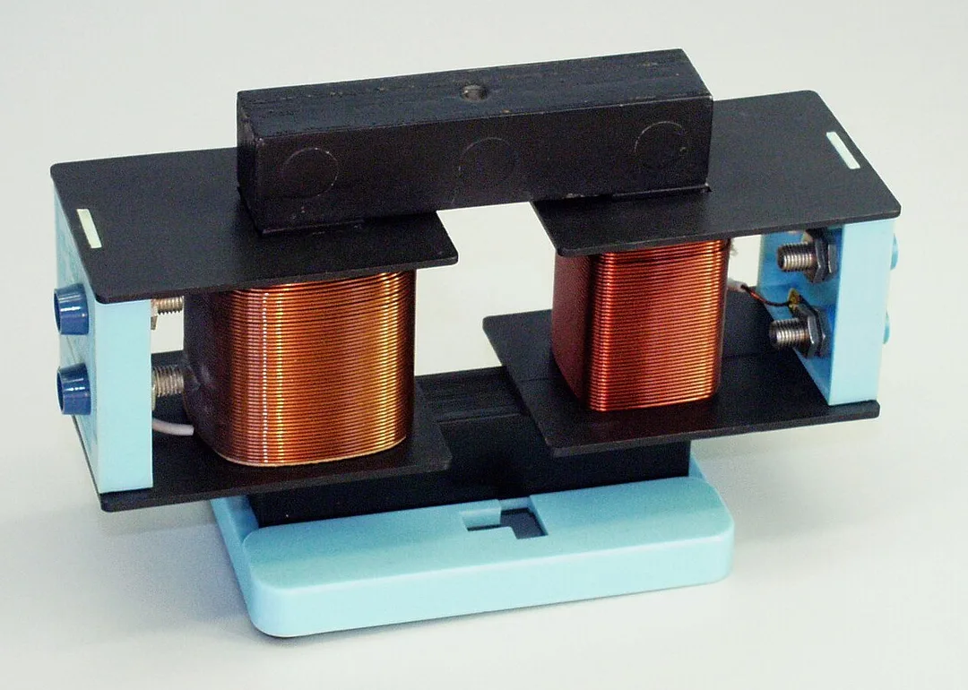
A transformer is electromagnetic induction with nothing moving. It has a primary coil and a secondary coil wound on an iron core. AQA says iron is used because it is easily magnetised. An alternating current in the primary coil makes a changing magnetic field in the iron core. That changing field passes through the secondary coil and induces a p.d. in it.
This is why transformers need AC. A steady DC supply gives a steady field and no continuing induced p.d. in the secondary. The p.d. across each coil is linked to the number of turns by:
Vp ÷ Vs = np ÷ ns
Here Vp and Vs are the p.d.s across the primary and secondary, and np and ns are the numbers of turns. A step-up transformer has more turns on the secondary, so Vs is larger than Vp. A step-down transformer has fewer turns on the secondary, so Vs is smaller than Vp. If a transformer is 100% efficient, the power output equals the power input:
Vs × Is = Vp × Ip
Step-up and step-down transformers are the backbone of the National Grid. Step-up transformers increase the p.d. from the power station to the transmission cables, and step-down transformers reduce it to a much lower value for homes. UK mains is 230 V at 50 Hz, while large power lines run at 400 kV or 275 kV, with local lines at 132, 66, 33 and 11 kV.
Why such high p.d.s? For the same power, a higher p.d. means a smaller current (P = V I), and less energy is wasted heating the cables (P = I² R). Large power transformers are very efficient, with average efficiency above 99%. You will practise these calculations in the maths section below.
The generator effect appears elsewhere too. A moving-coil microphone uses it: sound makes the coil move in a magnetic field, and the pressure variations become variations in current. A car alternator uses the engine belt to spin an electromagnet inside fixed coils, and diodes turn the output into DC to charge the 12 V battery. Electric cars use regenerative braking, which runs the motor as a generator.
Exam tips and common mistakes
These are the slips that cost marks on electromagnetic induction questions.
- Say "induced potential difference". If the circuit is not complete, only a p.d. is induced; a current needs a complete circuit.
- A still magnet gives no p.d. Do not write that a magnet inside a coil "makes electricity". There must be relative movement or a changing field.
- Say "more turns", not "thicker wire" or "bigger coil". Turns are the factor on the specification.
- More turns or a stronger magnet increase the output, not the efficiency. Do not mix up the two words.
- Transformers need AC. A steady DC supply will not keep inducing a p.d. in the secondary coil.
- Step-up means more turns on the secondary. The p.d. goes up, but the current goes down, because the power stays (almost) the same.
- Dynamo gives DC; alternator gives AC. That is AQA's wording, even though a bike "dynamo" is really an alternator.
- Always give units and a sensible number of significant figures. Show the equation, the substitution and the answer.
Exam-style questions on electromagnetic induction
Try each question in your head or on paper first, then tap to check the model answer.
Describe how you would show that a moving magnet can induce a current in a coil. (4 marks)
Connect the ends of a coil of wire to a centre-zero galvanometer to make a complete circuit (1). Push a bar magnet into the coil and watch the meter (1). The needle deflects while the magnet is moving, and goes back to zero when the magnet is held still (1). Pulling the magnet out gives a deflection in the opposite direction (1).
Explain why the needle deflects the opposite way when the magnet is pulled out of the coil. (2 marks)
The magnetic field through the coil is now changing in the opposite way (1), so the induced p.d. and current are in the opposite direction (1).
Give three ways to increase the induced potential difference. (3 marks)
Move the magnet (or coil) faster (1); use a stronger magnet (1); use a coil with more turns (1).
Explain why electricity is transmitted across the National Grid at 400 kV. (3 marks)
For the same power, a higher p.d. means a smaller current (1). A smaller current causes less heating in the cables, because the power wasted is I²R (1). So less energy is wasted and the transmission is more efficient (1).
Maths practice questions
These 12 questions use the equations from this article. Each one is graded with stars (★ easiest, ★★★ hardest). Tap a question to reveal the worked solution. Where a number is marked "(given)", it is a value stated in the question, not a real measurement. Use g = 9.8 N/kg.
Vp ÷ Vs = np ÷ ns
Vs × Is = Vp × Ip
P = V × I
P = I² × R
efficiency = useful power output ÷ total power input
E = P × t
Ep = m × g × h
f = 1 ÷ T
On the AQA Physics equation sheet (Higher tier) you are given the two transformer equations, but you must learn the others.
1. ★ A transformer has 1,000 turns on the primary and 50 on the secondary. The primary is connected to 230 V AC. Calculate Vs and say whether it is step-up or step-down.
Vs = Vp × ns ÷ np = 230 × 50 ÷ 1000 = 11.5 V. Vs is less than Vp, so it is a step-down transformer.
2. ★ A 12 V model-railway transformer runs from 230 V mains and its primary has 2,300 turns. How many turns are on the secondary?
ns = np × Vs ÷ Vp = 2300 × 12 ÷ 230 = 120 turns.
3. ★ An oscilloscope trace from an alternator shows one complete cycle every 0.020 s. What is the frequency? A bike dynamo trace shows one cycle every 0.050 s. What is its frequency?
f = 1 ÷ T = 1 ÷ 0.020 = 50 Hz (the same as UK mains). For the bike dynamo, 1 ÷ 0.050 = 20 Hz.
4. ★ A bike dynamo is rated 6.0 V, 3.0 W. (a) What is the current in the lamp circuit? (b) How much energy is transferred to the lights in a 1-hour ride?
(a) I = P ÷ V = 3.0 ÷ 6.0 = 0.50 A. (b) E = P × t = 3.0 × 3600 = 10 800 J (10.8 kJ).
5. ★★ A power-station generator produces 25 kV (given); the grid cable is at 400 kV. (a) What is the turns ratio ns : np? (b) If np = 500, find ns.
(a) 400 ÷ 25 = 16 : 1. (b) ns = 500 × 16 = 8,000 turns.
6. ★★ An ideal (100% efficient) transformer has Vp = 230 V, Ip = 0.50 A and Vs = 11.5 V. Find Is.
Vs × Is = Vp × Ip, so Is = 230 × 0.50 ÷ 11.5 = 10 A. (The power is 115 W on both sides.)
7. ★★ A 12 V, 60 W lamp is run from 230 V mains through a 100% efficient transformer. What is the current in the lamp, and what current is drawn from the mains?
Is = 60 ÷ 12 = 5.0 A. Ip = 60 ÷ 230 = 0.26087, so 0.26 A (2 s.f.).
8. ★★ A real transformer has an input of 230 V, 0.30 A and an output of 12 V, 5.5 A. What is its efficiency?
Input power = 230 × 0.30 = 69 W. Output power = 12 × 5.5 = 66 W. Efficiency = 66 ÷ 69 = 0.9565 = 96% (2 s.f.; 95.7% to 3 s.f.). The missing 3 W heats the coils and core.
9. ★★ Dinorwig delivers 1,728 MW for 5.0 hours. How much energy is that in MWh and in joules?
E = P × t = 1728 MW × 5.0 h = 8,640 MWh (8.64 GWh). Since 1 MWh = 1,000,000 W × 3,600 s = 3.6 × 10⁹ J, 8640 × 3.6 × 10⁹ = 3.1 × 10¹³ J (3.11 × 10¹³). This is below the station's 9.1 GWh storage capacity, as it should be.
10. ★★★ A small hydro scheme: 1,000 kg of water falls 50 m every second (given) and the turbine and generator are 90% efficient (given). What is the electrical power output?
Ep each second = m × g × h = 1000 × 9.8 × 50 = 490 000 J, so the power input is 490 kW. Output = 0.90 × 490 kW = 441 kW = 440 kW (2 s.f.).
11. ★★★ 500 MW is sent along a line of resistance 0.50 Ω (given). Compare the current and the heating loss at 25 kV and at 400 kV.
I = P ÷ V. At 25 kV: 500 × 10⁶ ÷ 25 000 = 20 000 A. At 400 kV: 500 × 10⁶ ÷ 400 000 = 1,250 A. Loss P = I²R. At 25 kV: 20 000² × 0.50 = 2.0 × 10⁸ W (200 MW, 40% of the power). At 400 kV: 1,250² × 0.50 = 781 250 W ≈ 0.78 MW (about 0.16%). The current is 16 times smaller, so the loss is 16² = 256 times smaller.
12. ★★★ A wind turbine's generator gives 2.0 MW at 690 V (given). A transformer at the tower base steps this up to 33 kV. (a) What is the turns ratio ns : np? (b) What is the current at 690 V and at 33 kV (assume 100% efficient)? (c) If the generator is 98% efficient, what mechanical power must the blades supply?
(a) 33 000 ÷ 690 = 47.83, so about 48 : 1 (47.8). (b) At 690 V: 2.0 × 10⁶ ÷ 690 = 2898.6, so about 2,900 A. At 33 kV: 2.0 × 10⁶ ÷ 33 000 = 60.6, so about 61 A. (c) Input = 2.0 MW ÷ 0.98 = 2.0408 MW, so about 2.04 MW. About 41 kW is wasted as heat.
Test yourself on electromagnetic induction
If you enjoyed this hands-on practical, another one that makes electricity without a power supply is the lemon battery experiment. And if you want to see induction in a modern machine, the physics of electric cars explains regenerative braking.
Frequently asked questions about electromagnetic induction
What is electromagnetic induction in simple terms?
Electromagnetic induction is making a potential difference in a wire by moving a magnet and the wire relative to each other, or by changing the magnetic field around the wire. If the wire is part of a complete circuit, a current flows. AQA GCSE Physics calls this the generator effect.
What are the three factors that affect the size of the induced potential difference?
The size of the induced potential difference increases when the magnet or coil moves faster, when the magnet is stronger, and when the coil has more turns. Some courses also mention a larger coil area. All of these make the magnetic field through the coil change more quickly.
Why does the galvanometer needle move the other way when the magnet is pulled out?
Pulling the magnet out changes the magnetic field through the coil in the opposite way to pushing it in. The induced p.d. and current therefore reverse direction, so the needle deflects the opposite way. This follows Lenz's law: the coil always opposes the change.
What happens if the magnet is held still inside the coil?
Nothing is induced, and the galvanometer reads zero. The magnetic field through the coil is not changing, so there is no induced p.d. and no current. Electromagnetic induction needs relative movement or a changing field, not just the presence of a magnet.
Why is a centre-zero galvanometer used?
A centre-zero galvanometer has its zero in the middle of the scale, so the needle can swing to the left or the right. This lets you see the direction of the induced current as well as its size. An ordinary meter with zero at one end could not show a reversed current.
Is a bicycle dynamo AC or DC?
A traditional bicycle bottle dynamo produces AC, because a permanent magnet spins inside a fixed coil, so the induced p.d. reverses each half-turn. It is really a low-power magneto. Some newer models include a rectifier to give DC for charging phones or GPS units.
What is the difference between an alternator and a dynamo?
In AQA GCSE Physics, an alternator generates AC and uses slip rings with brushes, while a dynamo generates DC and uses a split-ring commutator that swaps the connections every half-turn. The output of a dynamo varies in size but never reverses direction.
Why do transformers only work with alternating current?
A transformer works because a changing current in the primary coil makes a changing magnetic field in the iron core, which induces a p.d. in the secondary coil. Steady direct current makes a steady field, so no continuing p.d. is induced in the secondary.
Is electromagnetic induction in GCSE Combined Science?
In AQA, electromagnetic induction and transformers are in section 4.7.3 of GCSE Physics, marked physics only and Higher tier only, so they are not in AQA Combined Science. Other exam boards organise their courses differently, so check your own specification.