Electromagnetic induction
Electromagnetic induction is the process of generating an electric current in a conductor by exposing it to a changing magnetic field. This phenomenon was first discovered by Michael Faraday in 1831.
According to Faraday’s law of electromagnetic induction, an electric current is induced in a conductor when the magnetic field surrounding the conductor changes with time. The induced current flows in such a direction as to oppose the change in magnetic field that produced it. This is known as Lenz’s law.
Demonstrate electromagnetic induction by a simple activity
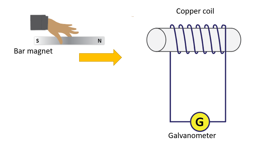
The above activity shows that there is a deflection in the galvanometer for every motion where the relative distance between the coil and the magnet changes.
When a current flows through the galvanometer, it generates a deflection. A source of electromotive force must be present in the circuit to generate current. However, there is no such source in the preceding circuit.
The relative motion of the coil and the magnet has caused an electromotive force in this example. An induced electromotive force is one such electromotive force.
When the magnet and the coil move closer or further apart, the magnetic field lines connected to the coil either increase or decrease. Because a deflection in the galvanometer is only noticed in such cases, one can assume that there must be a variation in the magnetic field lines connected to the coil in order to create an electromotive force.
When the magnet is moved quickly, the galvanometer deflects more than when it is moved slowly because the electromotive force created in the coil is exactly proportional to the rate of change of the magnetic field lines.
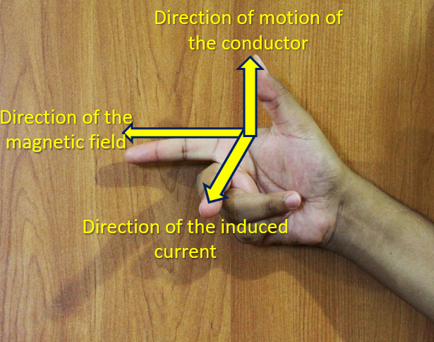
Fleming’s right-hand rule
Fleming’s right-hand rule is a technique used to determine the direction of the induced current. It states that if you point your right thumb in the direction of the magnetic field, and your fingers in the direction of motion of the conductor, then the direction of the induced current will be perpendicular to both the magnetic field and the direction of motion.
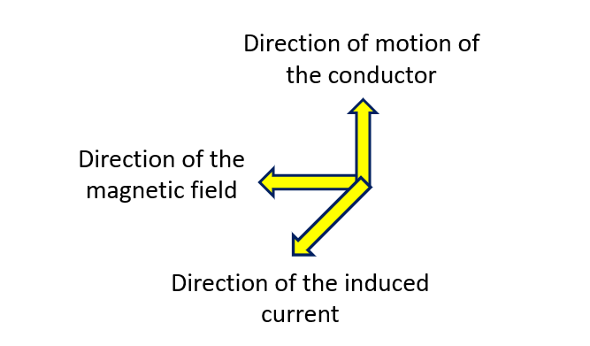
The middle finger of the right hand indicates the direction of the current flowing through the conductor when the first three fingers are positioned perpendicular to one another, with the thumb pointing in the conductor’s direction of motion and the index finger pointing in the direction of the magnetic field that intersects the conductor.
Fleming’s right-hand rule in a diagram
Applications of Electromagnetic Induction
Electrical generators
An electrical generator, also known as a dynamo, is a device that converts mechanical energy into electrical energy by the principle of electromagnetic induction. The generator consists of a rotating magnet called the rotor and a stationary coil of wire called the stator.
When the rotor rotates, it generates a changing magnetic field that passes through the stationary coil. This changing magnetic field induces an electromotive force (EMF) in the coil, according to Faraday’s law of electromagnetic induction. The induced EMF causes an electrical current to flow in the coil, which can be used to power electrical devices.
The amount of electrical energy generated by the generator depends on several factors, including the strength of the magnetic field, the speed of rotation, and the number of turns in the coil. Increasing any of these factors will increase the output voltage and current of the generator.
In most electrical generators, the magnetic field is produced by an electromagnet rather than a permanent magnet. The electromagnet is created by passing a direct current through a coil of wire, which produces a magnetic field. This magnetic field is then used to induce an EMF in the stator coil as the rotor rotates.
To produce a continuous supply of electrical energy, the generator must be connected to a source of mechanical energy, such as a turbine or an engine. The mechanical energy is used to rotate the rotor, which in turn generates electrical energy in the stator coil.
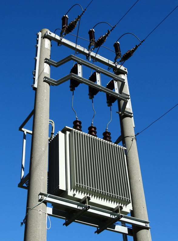
Transformers
Transformers use the principles of electromagnetic induction to transfer electrical energy from one circuit to another. A transformer consists of two coils of wire wrapped around a common iron core. The coil connected to the input voltage source is called the primary coil, while the coil connected to the output circuit is called the secondary coil.
When an alternating current flows through the primary coil, it generates a magnetic field that alternates in direction. This alternating magnetic field then induces an alternating voltage in the secondary coil, according to Faraday’s law of electromagnetic induction.
The magnitude of the induced voltage in the secondary coil depends on the ratio of the number of turns in the primary and secondary coils. If the secondary coil has more turns than the primary coil, the induced voltage will be greater than the input voltage, and the transformer is called a step-up transformer. Conversely, if the secondary coil has fewer turns than the primary coil, the induced voltage will be less than the input voltage, and the transformer is called a step-down transformer.
The alternating current flowing in the primary coil also generates an alternating magnetic field in the iron core. This magnetic field links the primary and secondary coils, allowing energy to be transferred from the primary circuit to the secondary circuit.
Transformer diagram
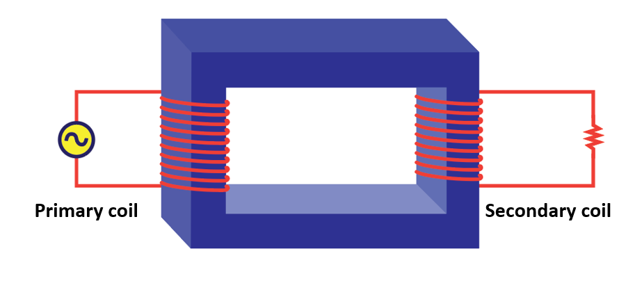
The iron core is used to enhance the magnetic coupling between the two coils, and to minimize energy losses due to eddy currents and hysteresis. Eddy currents are induced currents that flow in the iron core, and hysteresis is the energy loss due to the magnetic properties of the core material.
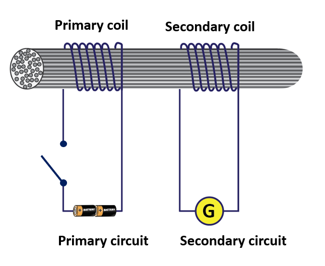
Demonstrate the process in a transformer
Induction heating
Electromagnetic induction is used in induction heating to heat a metal by generating an alternating magnetic field in it.
Magnetic levitation
Electromagnetic induction is used to create magnetic fields that levitate objects such as trains and maglev vehicles.
Eddy current testing
Electromagnetic induction is used in non-destructive testing to detect flaws in metal objects by measuring eddy currents induced in them.
Wireless charging
Electromagnetic induction is used in wireless charging to transfer electrical energy wirelessly from a charger to a device.